The Canon PowerShot SX60 HS is a versatile camera, offering a powerful 65x zoom and impressive features. Users explore lakes like Cannon Lake, while others seek printer solutions.
Overview of the Camera
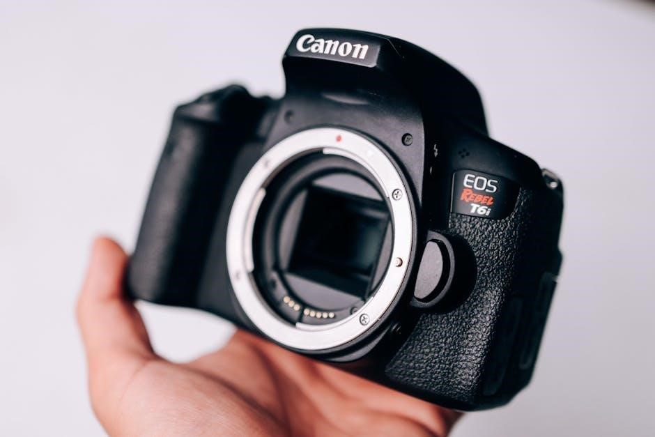
The Canon PowerShot SX60 HS stands as a robust bridge camera, bridging the gap between compact point-and-shoots and more complex DSLR systems. It’s designed for enthusiasts seeking extended zoom capabilities and creative control. Reports from Minnesota’s Cannon River and Lake highlight outdoor adventures, mirroring the camera’s versatility.
This model boasts a 16.3-megapixel High-Sensitivity CMOS sensor and DIGIC 6 Image Processor, delivering excellent image quality even in low-light conditions. Its substantial 65x optical zoom lens provides incredible reach, while Wi-Fi connectivity simplifies image sharing. The SX60 HS aims to be an all-in-one photographic solution.
Key Features and Specifications
The SX60 HS features a 16.3MP CMOS sensor, DIGIC 6 processor, and a remarkable 65x optical zoom (21-1365mm equivalent). It captures Full HD 1080p video at 30fps. Its 3.0-inch LCD screen offers clear viewing, and built-in Wi-Fi enables easy image transfer to mobile devices.
The camera utilizes an ED05F-08-8 Lithium-Ion battery, crucial for power. It supports various shooting modes, including Auto, Scene, and Manual. Connectivity includes USB and Wi-Fi, aligning with modern digital workflows, much like finding the right Canon printer for home or office.

Getting Started with Your SX60 HS
Begin your journey by unpacking the camera, charging the ED05F-08-8 battery, and inserting it correctly. Explore settings for optimal performance, like fishing Cannon Lake!
Unboxing and Initial Setup
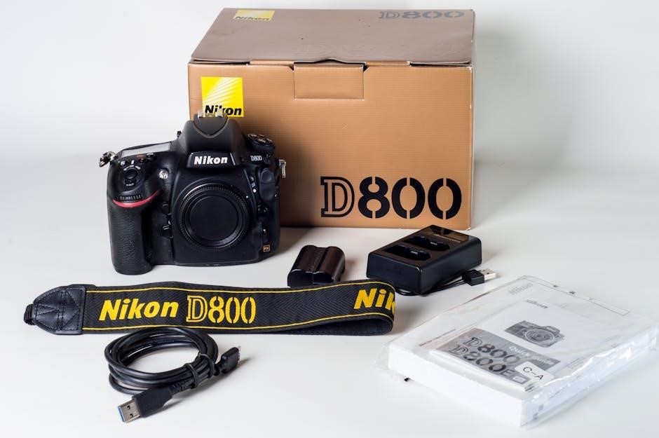
Carefully unpack your Canon PowerShot SX60 HS, ensuring all included accessories are present – camera body, battery, battery charger, and wrist strap. Before first use, inspect the camera for any physical damage sustained during shipping. Initial setup involves inserting the battery (refer to dedicated section) and a compatible memory card. Power on the camera and follow the on-screen prompts to select your preferred language, date, and time. Consider registering your camera online for warranty benefits and access to Canon’s support resources, much like exploring lakes such as Cannon Lake.
Charging the Battery (ED05F-08-8 Lithium-Ion)
Utilize the provided battery charger to fully charge the ED05F-08-8 Lithium-Ion battery before initial use. Connect the charger to a standard wall outlet. The charging indicator light will illuminate, typically red during charging and turning green upon completion. A full charge typically takes several hours. Avoid interrupting the charging process. Do not expose the battery to extreme temperatures. Proper battery care, similar to maintaining equipment for fishing on Cannon Lake, extends its lifespan and ensures optimal performance.
Inserting and Removing the Battery
To insert the battery, locate the battery compartment latch on the camera’s bottom. Slide the latch to unlock and open the compartment. Align the battery contacts with the markings inside, and gently push the ED05F-08-8 Lithium-Ion battery into place until it clicks. To remove, slide the latch again and press the battery release lever. Handle the battery with care, avoiding any forceful actions. Proper handling, much like maintaining downriggers, ensures longevity.
Understanding the Camera Controls
Mastering the SX60 HS controls—power, mode dial, shutter, and zoom—is key to unlocking its full potential. Like navigating a Canon printer setup, familiarity is crucial.
Power Button and Mode Dial
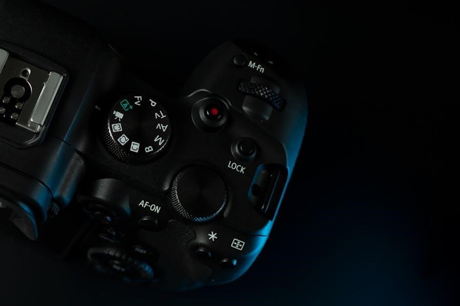
The Power Button, prominently located on the camera’s top panel, initiates and terminates camera operation. A firm, yet gentle press activates the SX60 HS, bringing the display to life. Adjacent to it resides the Mode Dial, a crucial control for selecting shooting modes.
Rotating this dial allows swift access to Auto, Scene, and Creative modes, tailoring the camera to various photographic scenarios. Like choosing a printer setting, selecting the correct mode optimizes performance. The dial’s clear markings ensure intuitive operation, even for beginners, mirroring the ease of Canon product registration.
Shutter Button and Zoom Control
The Shutter Button, centrally positioned on the camera grip, governs image capture. A half-press activates autofocus, while a full press releases the shutter, recording the photograph. Surrounding the shutter button is the Zoom Control, a lever enabling effortless magnification.
This control facilitates the SX60 HS’s impressive 65x optical zoom, bringing distant subjects into sharp focus – much like exploring different lakes. Precise zoom adjustments are achievable, mirroring the fine-tuning of Canon printer settings. Careful use enhances composition and creative possibilities.
Menu System Navigation
The Canon SX60 HS’s menu system is accessed via the MENU button on the rear panel. It’s logically organized into distinct tabs – Shooting, AF, Setup, and more – for intuitive browsing. Use the directional buttons to navigate, and the SET button to confirm selections.
This system allows customization of image quality, similar to selecting printer options. Exploring settings is key, much like discovering new fishing spots on Cannon Lake. Efficient navigation unlocks the camera’s full potential, mirroring the setup of a Canon Pixma MX700.
Shooting Modes Explained
The SX60 HS offers diverse shooting modes, from fully automatic simplicity to manual control, enabling creative expression like exploring the Cannon River’s beauty.
Auto Mode for Beginners
Canon’s Auto mode simplifies photography, intelligently selecting optimal settings for various scenes. This is perfect for users new to photography, eliminating complex adjustments. Like anglers spreading out on Cannon Lake, beginners can focus on composition without worrying about technical details. The camera automatically handles focus, exposure, and white balance, ensuring well-exposed, vibrant images. It’s ideal for everyday snapshots and capturing memories effortlessly. Auto mode prioritizes ease of use, allowing anyone to achieve pleasing results quickly, mirroring the simple joy of fishing a familiar spot.
Scene Modes (Portrait, Landscape, Sports)
Canon’s SX60 HS offers specialized Scene modes for optimized results in specific situations. Portrait mode softens backgrounds, emphasizing subjects, while Landscape mode maximizes depth of field for expansive views. Sports mode utilizes faster shutter speeds to freeze action, similar to capturing a quick fish on Cannon Lake. These presets adjust camera settings automatically, delivering tailored images. Selecting the appropriate scene mode ensures optimal image quality without manual adjustments, providing convenience and enhancing creative control for diverse photographic opportunities.
Creative Modes (Program, Aperture Priority, Shutter Priority, Manual)
For experienced photographers, the SX60 HS provides full creative control through Program (P), Aperture Priority (Av), Shutter Priority (Tv), and Manual (M) modes. Program mode offers suggested settings, while Av allows aperture control for depth of field. Tv controls shutter speed for motion blur or freezing action, like a downrigger’s movement. Manual mode grants complete command over both aperture and shutter speed, enabling precise image customization. These modes unlock artistic potential, mirroring the exploration found on the Cannon River.

Focusing and Image Quality
Achieving sharp images relies on autofocus modes like Single, Continuous, and Face Detection. Image stabilization minimizes blur, while ISO settings balance brightness and noise.
Autofocus Modes (Single, Continuous, Face Detection)
The SX60 HS offers several autofocus (AF) modes to suit various shooting scenarios. Single AF is ideal for stationary subjects, locking focus when the shutter button is half-pressed. Continuous AF tracks moving subjects, constantly adjusting focus for sharp results – perfect for sports or wildlife.
Face Detection AF prioritizes faces within the frame, ensuring portraits are crisp and clear. This mode automatically detects and focuses on faces, even in challenging lighting conditions. Experiment with these modes to optimize focus for different subjects and situations, enhancing overall image quality.
Image Stabilization Techniques
The Canon PowerShot SX60 HS incorporates Optical Image Stabilization, a crucial feature for sharp images, especially at its impressive 65x zoom range. This technology minimizes blur caused by camera shake, allowing for handheld shooting at slower shutter speeds.
Utilize the IS settings within the camera’s menu to select the appropriate stabilization mode. Consider using a tripod for maximum stability in low-light conditions or when employing the full zoom extent. Proper technique, like a firm stance, also contributes to sharper photos.
Understanding ISO Settings
ISO determines your camera’s sensitivity to light. Lower ISO values (like 100) produce cleaner images in bright conditions, while higher ISO settings (like 3200) are useful in low light, but introduce more noise or grain.
The SX60 HS allows for ISO Auto, letting the camera choose the optimal setting. Experiment with manual ISO control to balance brightness and image quality. Be mindful that increasing ISO compromises detail, so use it judiciously for sharper results.
Zoom Functionality and Range
The SX60 HS boasts a remarkable 65x optical zoom, bringing distant subjects closer; Consider digital zoom limitations for maintaining optimal image clarity.
Utilizing the 65x Optical Zoom
The Canon PowerShot SX60 HS’s 65x optical zoom is a standout feature, enabling photographers to capture detailed images of subjects far away without significant image degradation. Mastering this zoom requires practice; slowly zoom in to avoid abrupt transitions. Remember that at maximum zoom, image stabilization becomes crucial for sharp results, especially in lower light conditions. Explore various compositions, utilizing the zoom to isolate subjects or create compressed perspectives. Be mindful of potential camera shake and employ a stable shooting stance or tripod for optimal clarity when fully extended;
Digital Zoom Considerations
While the SX60 HS boasts a substantial 65x optical zoom, its digital zoom should be used cautiously. Digital zoom essentially crops and enlarges the image, leading to a reduction in image quality and increased pixelation. It’s best reserved for situations where optical zoom isn’t sufficient and a slight quality loss is acceptable. Prioritize optical zoom whenever possible for sharper, more detailed images. Understand that excessive digital zoom can render images unusable, particularly for larger prints or detailed viewing.
Recording Videos with the SX60 HS
The SX60 HS captures videos in various resolutions and frame rates, allowing creative flexibility. Utilize the zoom function carefully during recording for optimal results.
Video Recording Resolutions and Frame Rates
The Canon PowerShot SX60 HS offers a range of video recording options to suit diverse needs. Users can record in Full HD 1920×1080 at various frame rates, including 60fps, 30fps, and 24fps, providing smooth and cinematic footage.
Lower resolution options like HD 1280×720 are also available, suitable for sharing online or conserving storage space. The camera supports standard frame rates for natural-looking motion. Exploring lakes like Cannon Lake or considering printers doesn’t impact these video settings. Experimenting with different resolutions and frame rates allows for creative control over your videos.
Using the Zoom Function During Video Recording
The Canon PowerShot SX60 HS allows zooming during video recording, but it’s important to note that the zoom is digital beyond the 65x optical range. While recording, use the zoom lever around the shutter button to adjust the field of view.
Be aware that digital zoom can reduce image quality, especially at maximum magnification. Smooth zooming is recommended for professional-looking results; avoid abrupt changes. Fishing at Cannon Lake or printer choices don’t affect zoom functionality. Practice to master smooth zoom transitions during video capture.

Connectivity and Transferring Images
The Canon PowerShot SX60 HS connects via USB to computers and offers Wi-Fi for mobile app integration, simplifying image transfer and sharing experiences.
Connecting to a Computer via USB
To connect your Canon PowerShot SX60 HS to a computer using a USB cable, first ensure the camera is powered off. Locate the USB port on the camera, typically found under a protective cover. Connect one end of a standard USB cable to the camera’s port and the other end to a USB port on your computer.
Power on the camera. Your computer should recognize the SX60 HS as a removable storage device. You can then browse the camera’s files (photos and videos) directly through your computer’s file explorer. Transfer images by simply copying and pasting them to your desired location on your computer. Remember to safely eject the camera from your computer before disconnecting the USB cable.
Wi-Fi Connectivity and Mobile App Integration
The Canon PowerShot SX60 HS offers Wi-Fi connectivity, enabling seamless image transfer and remote camera control via the Canon Camera Connect mobile app. Download the app from your device’s app store (iOS or Android).
On the camera, navigate to the Wi-Fi settings in the menu. Select your home network and enter the password when prompted. Once connected, launch the Camera Connect app on your smartphone or tablet. The app will automatically detect your SX60 HS. You can then transfer photos and videos wirelessly, or even control the camera remotely for self-portraits or group shots.

Customizing Camera Settings
Personalize your SX60 HS by adjusting image quality, size, date, time, and button functions within the camera’s menu system for optimal results.
Adjusting Image Quality and Size
Fine-tune your photos with the SX60 HS’s image quality settings. Choose from various resolutions and compression levels to balance file size and detail. Higher resolutions capture more information, ideal for large prints or cropping, but require more storage space. Lower resolutions are suitable for web sharing or when memory is limited.
Select image sizes like Large, Medium, or Small, impacting the number of photos you can store. Experiment to find the sweet spot between quality and capacity. Consider the intended use of your images when making these adjustments for optimal results and efficient storage.
Setting the Date and Time
Accurate date and time stamping is crucial for organizing and referencing your photos. Access the camera’s menu to locate the date/time setting. You can manually input the current date and time, or enable automatic setting via a connected smartphone using Wi-Fi connectivity.
Ensure correct time zone selection for accurate metadata. Incorrect settings can cause confusion when reviewing images later. Regularly check and adjust the date and time, especially after traveling across time zones, to maintain proper image organization and chronological order.
Customizing Button Functions
The SX60 HS allows personalized control by reassigning functions to specific buttons. Access the ‘Custom Functions’ menu within the camera settings to tailor the button layout to your shooting style. This feature enhances efficiency, placing frequently used settings at your fingertips;
Customize direct access to features like ISO, white balance, or focus modes. Experiment with different configurations to optimize workflow. Remember to note your changes for easy reversion if needed, ensuring a comfortable and intuitive shooting experience tailored to individual preferences.
Troubleshooting Common Issues
Common problems include power failures or focusing difficulties. Downrigger issues may occur, but solutions exist. Check battery connections and settings for quick fixes.
Camera Not Powering On
If your Canon PowerShot SX60 HS fails to power on, begin with the simplest checks. Ensure the battery is correctly inserted, referencing the ED05F-08-8 Lithium-Ion battery specifications. Verify the battery has sufficient charge; attempt charging using a known-good USB cable and power adapter.
Confirm the charging indicator illuminates. If not, try a different USB port or adapter. A completely discharged battery may take time to respond. If still unresponsive, attempt a hard reset by removing and reinserting the battery. Consider external factors; extreme temperatures can affect battery performance.
Focusing Problems
Experiencing focusing issues with your Canon PowerShot SX60 HS? First, ensure the lens is clean and free of obstructions. Select an appropriate autofocus (AF) mode – Single, Continuous, or Face Detection – based on your subject. Verify sufficient lighting; low light can hinder autofocus performance.
Try half-pressing the shutter button to initiate autofocus. If the camera struggles, manually select a focus point. Consider utilizing image stabilization, especially at longer zoom ranges. Remember, subjects too close to the lens may exceed the minimum focusing distance.

Maintaining Your Canon PowerShot SX60 HS
Regular cleaning of the lens and body is crucial for optimal performance. Proper battery care, including storage, extends its lifespan and camera functionality.
Cleaning the Lens and Body
To maintain optimal image quality, regularly clean the lens with a soft, lint-free cloth. Gently wipe away dust and fingerprints, avoiding harsh chemicals or abrasive materials. For stubborn smudges, use a lens cleaning solution specifically designed for camera lenses. The camera body can be cleaned with a slightly damp cloth; ensure it’s not overly wet.
Avoid spraying liquids directly onto the camera. Pay attention to crevices where dust can accumulate. Regularly inspect and clean the viewfinder window for clear viewing. Proper cleaning ensures longevity and consistent performance, allowing you to continue capturing memorable moments with your Canon PowerShot SX60 HS.
Battery Care and Storage
To maximize battery life (ED05F-08-8 Lithium-Ion), avoid extreme temperatures and fully discharge it before long-term storage. Store the battery in a cool, dry place, ideally around 68°F (20°C). Do not leave the battery fully charged for extended periods, as this can degrade its capacity.
Regularly cycle the battery – charge and discharge it a few times – to maintain its health. Avoid short-circuiting the terminals and never disassemble the battery pack. Proper battery care ensures reliable power for your Canon PowerShot SX60 HS during your photographic adventures.
Canon Product Registration and Account Management
Registering your SX60 HS online unlocks support and benefits. Managing your Canon account provides access to services, updates, and potential exclusive offers for registered users.
Registering Your Camera Online
Canon encourages users to register their PowerShot SX60 HS online through the official Canon website. This simple process links your camera to your Canon account, providing access to valuable resources. Registration confirms ownership, facilitates warranty claims, and ensures you receive important product updates and notifications.
Furthermore, registered owners often gain access to exclusive promotions and support materials. The process typically requires your camera’s serial number and proof of purchase. Don’t delay – registering your SX60 HS enhances your ownership experience and streamlines future interactions with Canon support.
Managing Your Canon Account
Your Canon account serves as a central hub for all your Canon product information and support needs. Through your account, you can update your contact details, track registered products like the PowerShot SX60 HS, and access download resources.
Managing your account also allows you to view warranty status, access exclusive content, and participate in Canon’s online community. Ensure your password is secure and regularly review your account settings. A well-managed account simplifies future interactions with Canon and maximizes your product benefits.
Exploring Additional Resources
Canon’s support website and online forums offer extensive help, troubleshooting, and community discussions for your PowerShot SX60 HS camera experience.
Canon Support Website
The official Canon support website is an invaluable resource for PowerShot SX60 HS owners. Here, you’ll discover a comprehensive library of downloadable manuals, including the complete digital camera manual, offering detailed guidance on every function.
Furthermore, the site provides frequently asked questions (FAQs), troubleshooting guides addressing common issues – like powering on or focusing problems – and software/driver updates to ensure optimal performance. Canon also offers direct contact options, including phone and email support, for personalized assistance with your SX60 HS.
Online Forums and Communities
Numerous online forums and communities dedicated to Canon cameras, and specifically the PowerShot SX60 HS, offer a wealth of user-generated knowledge. These platforms are excellent for seeking advice, sharing experiences, and finding solutions to problems not covered in the official manual.
Users discuss everything from optimal settings for Cannon Lake photography to troubleshooting downrigger issues, and even printer compatibility. You can find tips, tricks, and workarounds from fellow enthusiasts, fostering a collaborative learning environment beyond the standard digital camera manual.